Injection Mould Tools Explained - Why Is Correct Design so Important
The core & cavity design of the plastic injection mould tool is what gives the final product its shape, but there are several other functions of the tool that are crucial for the correct formation of the end product.
The tool places a large role in the correct cooling down rate of the moulded plastic part. If a plastic material sets at the wrong speed, distortion and stress may occur. The material of the tool should be chosen to keep cooling down rate in mind. Some plastic materials may need to be moulded in a water cooled tool.
Below you'll see a tool with a detailed explanation of all its components and their function in the injection moulding process. Hover over each part to see an explanation of its function. You may want to read our page about the injection moulding process first, or watch the injection moulding video!
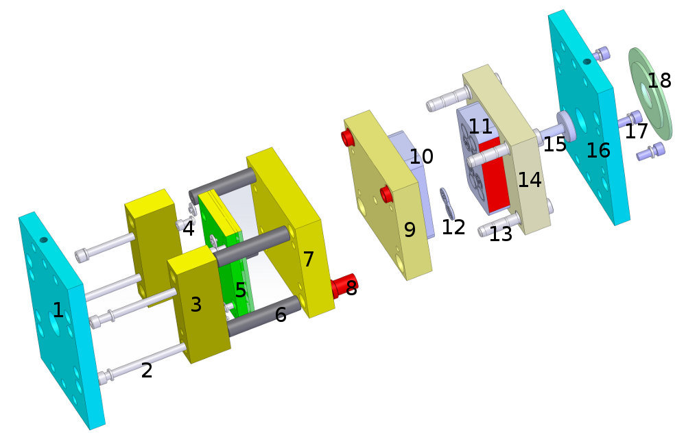
| 1. Moving half back plate. | Moving half support plate. Fits the moving platen of the injection moulding machine and provides the framework for the core or cavity to be mounted on. When open, the moulded part can be ejected. |
| 2. Bolts | |
| 3. Risers | Provide space for the ejector plate to move. |
| 4. Ejector plate feet. | These create a small gap between the fixed plate and the ejector plate to prevent the accumulation of dirt. |
| 5. Ejector locating plate & ejector plate retainer | Ejector locating plate & ejector plate retainer. The locating plate guides the ejector pins to the correct place and the retainer prevents the ejector pins from pushing back too far. |
| 6. Bolster sleeves | These keep all the elements of the bolster together, square and aligned. |
| 7. Moving half support plate | Moving half support plate. Fits the moving part of the injection moulding machine and provides the framework for the core or cavity to be mounted on. When open, the moulded part can be ejected. |
| 8. Guide bushes | Provide a bearing surface for the guide pins, protecting the core plate from wear. |
| 9. Core retaining plate | The core can be mounted on top or recessed into this. |
10. Mould Core & 11. Mould Cavity |
The Mould Core & Cavity are the shaped sections in either half of the mould tool which give the plastic product its final shape. The hot molten material is injected into the core & cavity and then sets hard into shape. The design of the core & cavity is essential in the correct formation of the product.
Essential elements of the Core & Cavity are -
Gate: This is the point between the runner and the core & cavity. Often it is designed to be slightly narrower than the runner, so that the plastic there is thinner when it sets, forming a natural weak point for easier removal of the runners. The tool needs to be designed carefully so that gates are in the right place to ensure correct filling of the core & cavity. As the placement of gates always remains visible on the moulded part, the tool also needs to be designed in such a way that the gates don't detract from the aesthetics of the finished product.
Runner: Runners allow the passage of the molten plastic materials to the core & cavity. Runners can also be hot or cold. Hot runners are more expensive but provide much greater flexibility for the positioning of gates (because they allow a gate to be much smaller) and they also reduce wastage because the plastic inside the runner stays hot and is used for the next part." alt="Mould core. The core & cavity are the shaped sections in either half of the mould tool which give the plastic product its final shape. The hot molten material is injected into the core & cavity and then sets hard into shape. The design of the core & cavity is essential in the correct formation of the product. |
| 12. THE MOULDED PART | |
| 13. Guide pins | These are the pins on one half on the tool that slide into the holes in the other half. Guide pins ensure the two halves of the tool are correctly aligned so that the product is correctly formed. |
| 14. Cavity retaining plate | The core can be mounted on top or recessed into this. |
| 15. Sprue bush | This is the point of the tool where the plastic material is first injected into the cavity. Sprue bushes can be hot tip or cold tip. Cold tip sprue bushes are less costly to make but use more material; hot tips use less material and give greater moulding flexibility. |
| 16. Fixed half back plate | Fits the fixed platen of the injection moulding machine and provides the framework for the core or cavity to be mounted on. |
| 17. Bolts | |
| 18. Locating ring | This fits in a location hole on the fixed half platen of the injection moulding machine to ensure correct alignment of the tool and the machine. |
Our experienced designers design for production. That means they know their plastic injection mould tool options inside out and can take the restrictions and possibilities of the moulding process into consideration from the outset, designing products that are both attractive, functional and economical to manufacture.